Earth Mat Testing Procedure
Https Ewh Ieee Org R3 Atlanta Ias Testing 20and 20evaluation 20of 20grounding 20systems Pdf
Https Energiforskmedia Blob Core Windows Net Media 22861 Grounding Grid Integrity Energiforskrapport 2017 405 Pdf

Electrical Test Equipment Power Station To Plug Megger

Quotation Marks Commas Work Mats For Centers Scoot Activities Ela Test Prep Quotations Teaching Reading Skills Test Prep Strategies
Procedure Methods Of Earthing Circuit Globe
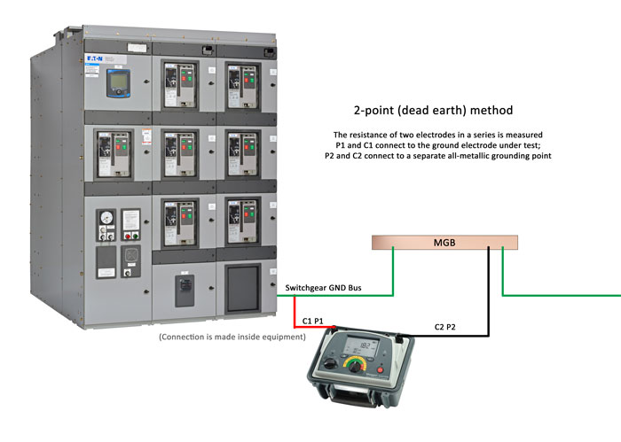
4 Important Methods Of Ground Resistance Testing

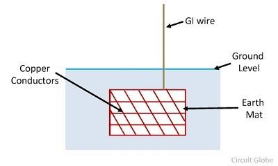
The measuring procedure described here uses the wenner method and uses the formula.
Earth mat testing procedure.

Free Magnet Activities For Kids Includes Sorting Mats And Worksheets That Help Kids Inv Magnet Activities Kindergarten Science Center Science Experiments Kids

Gre Vs The Mat Infographic Gre School Scholarship Graduate School

Morning And Dismissal Procedures Posters Morning Meeting Activities Homeschool Planning Poster
Https Www Ergon Com Au Data Assets Pdf File 0003 146037 Sp0510ver4 Pdf

Esd Grounding Methods For Anti Static Mats Elimstat Com
Http Images Pearsonclinical Com Images Pdf Assessmentreports Millerwhitepaper Pdf
How To Test An Esd Mat For Periodic Verification Video By American Hakko Youtube

Foundation Posibilities Jpg 4428 4599 Arsitek Bangunan Kanopi

Earth Day One Step Word Problems Within 20 Word Problems Subtraction Word Problems Math Word Problems

Comma Rules Centers Scoot Activity Work Mats Bundle Ela Test Prep Video Video In 2020 Comma Rules Ela Test Prep Test Prep Strategies

Did You Know 1 In 15 Homes Has Elevated Levels Of Radon The Good News Is It S Easy To Test And Mitigate Radon Mitigation Radon Gas Radon Testing
Tips For Effective Workplace Housekeeping In 2020 Health And Safety Poster Occupational Health And Safety Workplace Safety

These 2nd Grade Math Center Activities Are Perfect For Guided Math Rotations These Engaging Math Pu 3rd Grade Math 2nd Grade Math Games Math Center Activities

Scientific Method A Method Of Procedure That Has Characterized Natural Science Since Th Scientific Method Scientific Method For Kids Scientific Method Posters

Mass Spectrometry Wikipedia The Free Encyclopedia Mass Spectrometry Laboratory Science Teaching Chemistry

Download This Four 4s Challenge To Help Your Students Develop Order Of Operations Number Sense And Mat High School Math Teacher High School Math Math Teacher

Pin On Fantastic Mr Fox

4th Grade Symmetry Lesson Plans Math Lesson Plans Lesson Plans Math Lessons
3

The Final Science Fair Project Not So Wispy Dad The Single Guy Science Fair Board Kids Science Fair Projects Science Fair Projects

Free Earth Day Coloring And Activities Book To Download Fire Safety Worksheets Fire Safety Fire Prevention

Pin By Deona Madison On Learning Stuff For London In 2020 Science Fair Projects Science Fair Science Fair Projects Boards

Principles And Testing Methods Of Earth Ground Resistance Ee Publishers

Reading Word Graphs For Winter In 2020 Reading Words Winter Words Kindergarten Activities
Source : pinterest.com
